Rheology of Drilling Muds
Rheology is defined as the study of the deformation and flow of matter.
In drilling operations, the term rheology refers to the use of the shear stress/shear rate/time relationships of drilling fluids. Rheological properties are used to design and evaluate the hydraulics and to assess the functionality of the mud system.
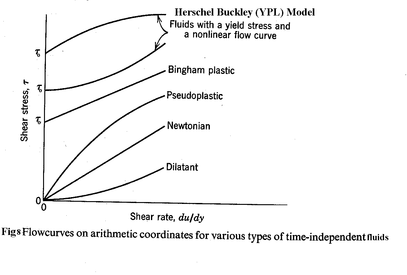
Everyone involved in the drilling operations knows that muds behave with non-Newtonian fluid flow properties as their viscosity is not only influenced by temperature and pressure but is also strongly related to the velocity at which the mud flows through the hydraulic system. The drilling fluid velocity and the resulting rate of shear at the walls of the conduits play an important role on the viscosity of the fluid pumped. For this reason, it is important to know the viscosity in the full range of shear rate usually considered for hydraulic calculations. There is a well characterized minimum stress, called yield point, below which flow does not occur. At low shear rates there is a typical non-linear relationship between shear stress and shear rate, which tends to be attenuated with the increase of shear rate.
Regular rheological measurements on drilling rigs are made by coaxial cylinder viscometer at two different speeds of 300 and 600 rpm. These represent the high shear rate region. Since drilling fluids are submitted to very different shear rates, from very low values in the mud pits to very high values through bit nozzles, the rheological parameters estimated based only on two measurements will lead to significant discrepancies such as yield point overestimation. Generally, the viscometer used on the oilfield allows measurements at 3, 6, 100, 200, 300 and 600 rpm. Of course, the fitting of the rheological model with these six measurements will provide parameters in better agreement with the HB curve shown in fig 8. Rheological models are useful tools to describe mathematically the relationship between shear stress and shear rate of a given fluid.
Traditionally, oil industry uses the Bingham and Ostwald de Waele (Power law) models to represent drilling fluid behavior. Also, standard API methods for drilling hydraulics assume either a Power Law or a Bingham Plastic model. In reality, most drilling muds correspond much more closely to the Modified Power Law or Herschel-Buckley rheological model. This distinction is particularly important for annular geometries typical of normal drilling conditions where shear rates are usually low. In these situations Power Law model underestimates while Bingham Plastic model overestimates frictional pressure drops. Herschel-Buckley rheological model presents more adequate rheological parameters, but the manipulation of the flow equation is not that easy.
Basic Definitions
Shear Rate: When fluid flow is laminar, fluid layers near the wall move at a slower rate than those further from the wall do. The layers near the center of the flow channel have the highest velocity. The velocity (speed) of a layer relative to the layers next to it is called the shear rate and is designated by the symbol g .
More precisely, the shear rate is the velocity gradient (change in velocity) measured perpendicular to the fluid flow (from the pipe/wellbore wall towards the center of the flow). It is calculated by dividing the distance from the wall into the velocity and then measuring the change in this velocity/distance ratio, e.g., ft/min divided by ft.
The dimensional unit of shear rate is inverse time, velocity divided by a distance, and is usually written as 1/sec or sec-1.
Range of Shear Rates in a Drilling Rig Circulating System
Location Approximate Shear rate, sec-1
Mud Pits <1 - 5
Annulus 5 - 200
Solids Removal Equipment and Inside Drill pipe
Pipe/Collars 100 - 10,000
Bit Nozzles up to >1,000,000
Shear Stress: In laminar flow, the resistance to flow developed between fluid layers, due to the shear rate, is called the shear stress and is designated by the symbol t.
The dimensional unit of shear stress is force per unit area, e.g., lbf/in2.
Pump pressure is related to the total shear stress developed in a circulating system. Increases in velocity and shear rate increase the shear stress and thus the pressure required to sustain the given flow rate from the mud pumps.
Viscosity: Viscosity is a measure of the relative thickness or thinness of a fluid and is defined as the ratio of the shear stress to the shear rate, designated by the symbol m . The relationship is given as,
m = t /g
The unit of viscosity is centipoise (cP) or millipascal × second (mPa× s).
Confusion over the meaning of a drilling fluid's viscosity is because viscosity is not constant throughout the circulating system. For most muds, the viscosity changes whenever the flow velocity changes. Therefore, at a constant pump output, the mud's viscosity is different in the drill pipe, the collars, through the bit, in different annular diameters, and in the surface system. Attempts to describe this changing viscosity resulted in different mathematical models,
The frictional pressure losses in pipes are important when optimizing the hydraulic program. A mathematical description of the viscous forces that create part of these frictional losses, and the friction losses caused by the pipe are modeled for laminar flow. These are the rheological models.
Viscosity is a general term used to define the internal friction generated by a fluid when a force is applied to cause it to flow. This internal friction, a result of the attraction of the molecules of a liquid, is known as shear stress; stronger the bond between the molecules, greater is the resistance to flow, the greater the viscosity. Shear stress is expressed in units of Force/ Area. When force is applied to cause a fluid to flow, the resultant effect is known as shear rate. It is defined as velocity gradient across adjacent fluid layers while in laminar flow. Shear rate has the dimensions of 1/time and is usually written sec-1.
Examples of Newtonian fluids are water, gasses, and high gravity oils.
The equation for shear stress, shear rate and viscosity for a Newtonian fluid has been determined experimentally in the following manner. Assume that a fluid is contained between two parallel plates as illustrated in fig 1. These plates have an area A, and are separated by a distance r. The upper plate, which is originally at rest, is set in motion in x direction at a constant velocity v. After a sufficient time has past to achieve steady
![]() Figure 1 Laminar flow of Newtonian fluid
Figure 1 Laminar flow of Newtonian fluid
motion, a constant force F is required to keep the upper plate moving at the constant velocity v. This was experimentally determined to be
![]() (1)
(1)
The term F/A is called shear stress, exerted on the fluid. Thus, shear stress is defined by,
![]() (2)
(2)
Note the area A is the area in contact with the fluid
The velocity gradient v/r is termed the shear rate:
![]() (3)
(3)
From the above equations one can see that the Newtonian model states that the shear stress t is directly proportional to the shear rate g . Giving the following equation:
t = m g (4)
Where m is a constant of proportionality and is the viscosity of the fluid.

Figure 2: Shear stress Vs Shear rate for a Newtonian fluid
The following is a derivation for the pressure loss of a Newtonian fluid. Consider a flow through pipe. The free body diagram (FBD) of the forces acting on the fluid is given as illustrated below,
Figure 3: FBD diagram to illustrate problemFrom our definition of shear stress the following derivation is possible:
![]() (5)
(5)
Where,
F1= P1 Ap (Ap is the Area of inlet of the pipe), Area of inlet = Area of outlet (6)
F2 = P2 Ap
r is the radius of the pipe
Using these definitions in Eq. (5) gives the following expression,
P1 Ap - P2 Ap = t 2p r D L Þ D P Ap = t 2p r D L
Solving this equation for shear stress gives,
![]() (7)
(7)
and finally,
![]() (8)
(8)
Where,
F is the Force
P is the pressure
A is the Area
Friction losses for a Newtonian fluid
Friction loss in a Laminar flow:
![]()
![]()
![]()
![]() (Field units) (10)
(Field units) (10)
![]()
![]() (Consistent units) (11)
(Consistent units) (11)
![]() Or
Or ![]() (Field units) (12)
(Field units) (12)
Where f is the fanning friction factor.
Non-Newtonian Models
Fluids that do not exhibit a direct proportionality between shear stress and shear rate are classified as non-Newtonian.
Most drilling fluids are non-Newtonian fluids. Their viscosity is too complex to be characterized by a single value. The apparent viscosity measured depends on the shear rate at which the measurement is made and the prior shear rate history of the fluid.
There are many equations for the pressure losses depending upon the type of model. All the different equations of pressure losses are not covered here. They are widely available.
Bingham Plastic Model (Laminar Flow)
A Bingham Plastic fluid has a yield point, which is the shear stress that has to be overcome so that the fluid can start to flow. This minimum value is t y. Once the yield point has been exceeded, the changes in shear rate are proportional to changes in shear stress and there is a constant of proportionality, which is called the plastic viscosity, m p.
t = m p g +t y; t > t y (13)
g = 0 ; -t y£ t £ t y (14)
t = m p g - t y ; t < -t y (15)
Following is graphical illustration of the above stated equations;
 Figure 4: Shear Rate Vs Shear Stress for a Bingham plastic fluid
The following is a derivation for pressure loss in a laminar flow for a Bingham plastic fluid.
Setting equation (8) and (3) into equation (13) yields
![]() (16)
(16)
After integrating and taking into account that for r = R, v = 0 we obtain,
![]() (17)
(17)
Considering the velocity profile for the Bingham plastic flow yields (setting r = ro)
 (18)
(18)
this is valid for 0 £ r £ ro
Where,
![]() (19)
(19)
This equation comes from equation (8)

Figure 5: Bingham plastic flow in a pipe
The flow rate is given by integrating over the radius of the pipe,
 (20)
(20)
After integrating Eq. (20) this yields
 (21)
(21)
Where po is the pressure necessary to initiate the flow and is defined by as,
![]() (22)
(22)
This is seen from equation (8).
One can further reduce Eq. (21) to the following (since the last term of equation (21) is very small, dP << Po)
![]() (23)
(23)
Substituting Q = v p R2 , R = d/2 and po into equation (23) yields:
![]()
![]() (24)
(24)
In field units the same equation is given as,
![]() (25)
(25)
Where,
m p Þ CP
t y Þ lb/100 ft2
d Þ in
v Þ fps
Pressure Loss in the annulus for a Bingham plastic fluid (laminar flow)
Using the hydraulic radius concept one can find the pressure loss in annular space for laminar flow, the derivation is not shown here but can be found in any good drilling book. The following equation for pressure loss is derived from the hydraulic radius concept for laminar flow,
Consistent units:
![]() (26)
(26)
Field units:
![]() (27)
(27)
![]()
Power-Law Model (laminar flow)
The power law model is given by the following equation,
t = K g n (28)
This equation is represented in the figure below,
![]()
Figure 6: Shear stress Vs Shear rate a for power law fluid: (a) pseudoplastic (b) dilatant
The constant K is a measure of the thickness of the fluid and is called the consistency index of the fluid; which is very closely related to the viscosity for low shear rates. At larger shear rates K is more of a measure of the amount of solids in the fluid. The parameter n is called the power-law exponent or the flow behavior index. This is a measure of the degree of deviation from Newtonian behavior. The Power-law model can be used to represent more than one fluid in the following manner:
n < 1 a pseudoplastic fluid
n = 1 a Newtonian fluid
n > 1 a dilatant fluid
The unit of K depends on the value of n.
K Þ
 or
or 
The figure below shows the velocity profile for three fluids with different power-law exponents.
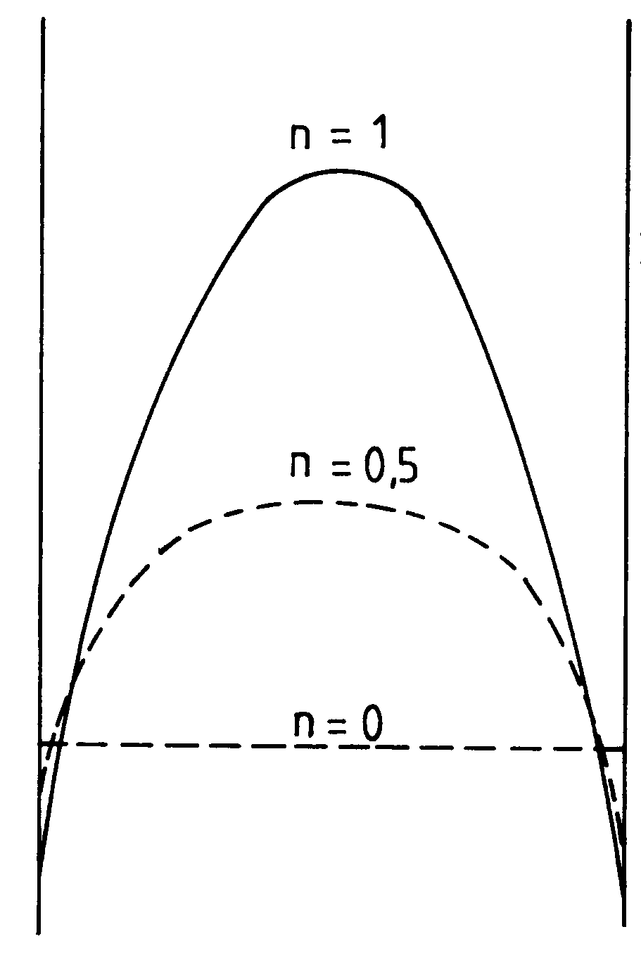
Figure 7: Velocity profile for a power law fluid
The friction pressure losses for a power law fluid in laminar flow is given by the following,
![]() (Consistent units) (29)
(Consistent units) (29)
![]() (Field units) (30)
(Field units) (30)
![]()
![]() (Consistent units) (31)
(Consistent units) (31)
![]() (Field units) (32)
(Field units) (32)
Pressure loss equations for turbulent flow
If one is to use the pressure loss equations for turbulent flow, one has to be sure that they are in turbulent flow regime. This can be done, by using the concept of effective viscosity. This is done because viscosity in practice is not constant but dependant on many factors such as velocity, pipe diameter, consistency factor etc. Following are the equations for the effective viscosity,
Effective viscosity for a Bingham plastic fluid
![]() (Consistent units) (33)
(Consistent units) (33)
![]() (Field units) (34)
(Field units) (34)
![]() (Consistent units) (35)
(Consistent units) (35)
![]() (Field units) (36)
(Field units) (36)
Effective viscosity for a Power Law fluid
![]() (Consistent units) (37)
(Consistent units) (37)
![]() (Field units) (38)
(Field units) (38)
![]() (Consistent units) (39)
(Consistent units) (39)
![]() (Field units) (40)
(Field units) (40)
Where,
v: velocity in fpm
K: consistency factor in lb/100 ft2
D: diameter of the annulus in inches
D: diameter of pipe in inches
m e: effective viscosity in cP
Once the effective viscosity has been established one needs to find out whether one is in laminar or turbulent flow to do this we use the following equation:
![]() (Field units) (41)
(Field units) (41)
The viscosity here is the effective viscosity.
Once this is known one can use the models for the turbulent flow or the laminar flow.
If Re < 1800 then the flow is a laminar flow
Between 1800 and 2100 the flow is a transition flow
Re > 2100 flow is turbulent
For turbulent flow the fanning equation may be applied. This is given as,
![]() (Consistent units) (42)
(Consistent units) (42)
![]() (Field units) (43)
(Field units) (43)
One can then use the friction factor curves that are available with the Reynolds number found from the effective viscosity, or one can proceed in the following manner;
Turbulent viscosity is given by
![]() (44)
(44)
This is an empirical equation. The reader can also use other empirical equations.
The Reynolds number is then expressed by the following equation,
For Pipe:
![]() (Field units) (45)
(Field units) (45)
For Annulus:
![]() (Field units) (46)
(Field units) (46)
Where velocity is expressed in fpm.
Substituting (44) in (45) and (46) the formulas for Reynolds number take the form,
For pipe:
![]() (Field units) (47)
(Field units) (47)
For annulus:
![]() (Field units) (48)
(Field units) (48)
For engineering purposes one may write
f = 0.046 Re-0.2 (49)
Where, the exponent for Reynolds number varies depending on the pipe roughness.
The constant 0.046 is an empirical constant.
Substituting (47) in (49) and then in (42) and rearranging gives us,
For pipe:
![]() (Field units) (50)
(Field units) (50)
For Annulus:
![]() (Field units) (51)
(Field units) (51)
Taking into account that velocity is expressed in fpm by,
For pipe:
![]() (Field units) (52)
(Field units) (52)
For annulus:
![]() (Field units) (53)
(Field units) (53)
Equation (50) and (51) can then be rewritten in the following form,
![]() (Field units) (54)
(Field units) (54)
![]() (Field units) (55)
(Field units) (55)
Where,
dp/dL (pressure loss) psi/ft
r (density) ppg
m p (plastic viscosity) cP
Q (flow rate) gpm
L (length) ft
D (diameter of annulus) in
d (diameter of pipe) in
Bingham Plastic model ![]()
Ostwald de Waele or Power Law model ![]()
Herschel-Buckley model ![]()
Development of Equations for Herschel-Buckley Model
The drilling engineer deals primarily with the flow of drilling fluids and cements down the circular bore of the drillstring and up the circular annular space between the drillstring and wellbore. In order to develop mathematical relation between flow rate and frictional pressure drop the following assumptions are made:
Fluid flowing in a pipe or a concentric annulus does not have a uniform velocity. The fluid velocity, immediately adjacent to the pipe walls will be zero, and fluid velocity most distant from the pipe walls will be maximum.
Pipe Flow
A relation between radius r & shear rate t can be obtained by consideration of Newton's Law of motion for a shell of fluid at radius r.
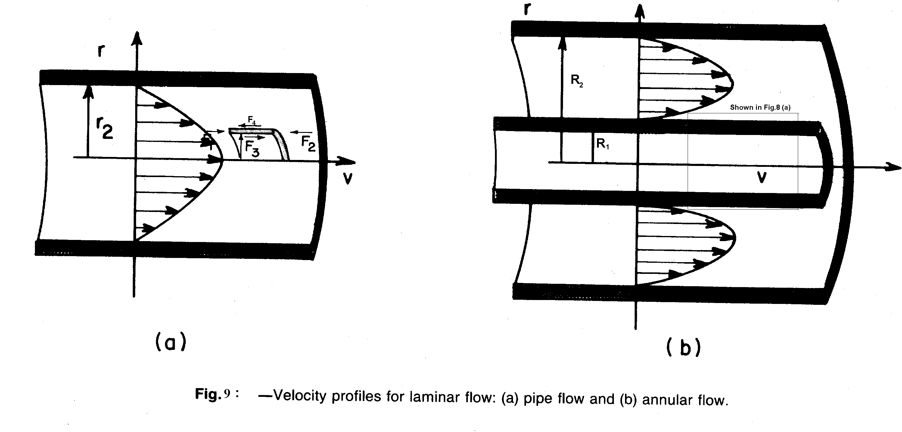
Fig.9 is a free body diagram of a shell of fluid of length D L and of thickness D r. The sign convention is from left to right and the velocity of flow is decreasing with increasing radius. Thus the next shell of fluid enclosed by the fluid element of interest is moving faster than the fluid element of interest. And the next shell of fluid enclosing the element of interest is moving slower than the element of interest. The force F1 applied by the fluid pressure at point 1 is given by
![]() (56)
(56)
And, the force F2 applied by the fluid pressure at point w is given by
![]() (57)
(57)
Here, the negative sign for the dp/dl is needed because the frictional pressure change D p is used to represent (p1-p2) rather than (p2-p1).
The frictional force exerted by the adjacent shell of fluid enclosed by the fluid element of interest is given by,
![]() (58)
(58)
Similarly, the frictional force exerted by the adjacent shell of fluid that encloses the fluid element of interest is given by
![]() (59)
(59)
If the fluid element is moving at a constant velocity, the sum of the forces acting on the elements must equal zero.
We obtain,
Expanding Eq.60 and dividing throughout by (2p rD rD L), and taking limit as D r® 0 yields;
![]() (61)
(61)
since dp/dl is not a function of r, Eq. (61) can be integrated with respect to r. Separating variables yields;
![]() (62)
(62)
upon integrating we obtain,
![]() (63)
(63)
Where C1 is the constant of integration. For pipe flow, the constant C1 must be zero if the shear stress is not to be infinite at r = 0.
![]() (64)
(64)
Eq. (64) relates shear stress and frictional pressure gradient at a given radius, is a consequence of the geometry of the system and does not require the assumption of a fluid rheological model.
The shear rate g for the sign convention used in the derivation is given by
![]() (65)
(65)
For Herschel-Buckley model
![]() (66)
(66)
Substituting Eq. (65) into Eq. (66) gives,
 (67)
(67)
Now, Eq. (64) in Eq. (67) yields,
 (68)
(68)
On rearranging, we have
 (69)
(69)
Now, Integrating


 (70)
(70)
If the pressure gradient, geometry and the YPL parameters are known Eq. (70) can be used to determine the velocity distribution within the drillpipe.
Annular Flow
Annular flow can be approximated using equations developed for flow through rectangular slots ( ie., representing the annulus as a slot). The slot flow equations are simpler to use and are resonably accurate as long as D1/D2 > 0.3. As shown in fig.8b the annular space can be represented as a narrow slot having an area A and height h, given by,
![]() (71)
(71)
and
![]() (72)
(72)
The relationship between shear stress and frictional pressure gradient for a slot can be obtained from consideration of the pressure and viscous forces acting on an element of fluid in the slot fig. 8b. If we consider an element of fluid having width W and thickness D y, the force F1 applied by the fluid pressure at point 1 is given by
![]() (73)
(73)
Similarly, the force F2 applied by the fluid pressure at point 2 is given by
![]()
![]() (74)
(74)
The frictional force exerted by the adjacent layer of fluid below the fluid element of interest is given by
![]() (75)
(75)
Similarly, the frictional force exerted by the adjacent layer of fluid above the fluid element of interest is given by,
 (76)
(76)
If the flow is steady, the sum of the forces acting on the fluid element must be equal to zero. Summing forces, we obtain
![]() (77)
(77)
and
 (78)
(78)
Expanding this equation and dividing throughout by (W D L D y) yields,
![]() (79)
(79)
Since, dp/dL is not a function of y, Eq. (79) can be integrated with respect to y. Separating variables, and integrating gives,
![]() (80)
(80)
Where, t (0) is the constant of integration that corresponds to the shear stress at y=0. For the sign convention used the shear rate g is given by
For Herschel-Buckley model
![]() (82)
(82)
Substituting Eq. (81) into Eq. (82) gives,
 (83)
(83)
Now, Eq. (80) into Eq. (83) yields,
 (84)
(84)
On rearranging, we have
 (85)
(85)
Now, Integrating


 (86)
(86)
Where,
t (0) is the shear stress exerted by the drilling fluid on the drillpipe, t dp, and is given by,
![]() (87)
(87)
If the pressure gradient, geometry and the YPL parameters are known Eq. (86) & (87) can be used to determine the velocity distribution within the drillpipe.
Herschel-Buckley model for Laminar or Turbulent Flow in Pipes and Annuli
As said before the Herschel-Buckley model usually gives the best fit of the viscometer data in comparison with the other rheological models. The most important equations of Herschel & Buckley model for friction pressure drop calculations, both in laminar and turbulent flow in circular and annular conduits are shown below;
Herschel-Buckley Model in Pipe
Evaluation Criterion for Laminar or Turbulent Flow
The equivalent Reynolds number is given by the following equation
![]() (88)
(88)
Where,
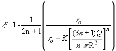 and (89)
![]() , (90)
, (90)
, (91)
![]() (92)
(92)
On substituting the Eqs. (89), (90), (91) & (92) in equation (88) we obtain,
Equivalent Reynolds number,
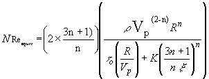 (93)
(93)
While the critical equivalent Reynolds number is given by;
 (94)
(94)
Where,
![]() ,
,
![]()
For ![]() the flow is considered laminar while,
the flow is considered laminar while,
For ![]() the flow is considered turbulent
the flow is considered turbulent
The pressure drop is calculated using the following Fanning expression:
![]() (95)
(95)
While the friction factor is determined by the following equation:
![]() (96)
(96)
Substituting Eqs. (93) and (96) in Eq. (95) we have
 (97)
(97)
Where, x is the correlation coefficient for the circular section.
The pressure drop is calculated using the following fanning equation:
![]()
While, the fanning friction factor is determined by using the relation of Schuh;
![]() (98)
(98)
where v and y are coefficient shown in the before section.
Herschel-Buckley Model for Flow in Annulus
Evaluation Criterion for Laminar or Turbulent Flow
The equivalent Reynolds number is given by the following equation
![]() (99)
(99)
Where,
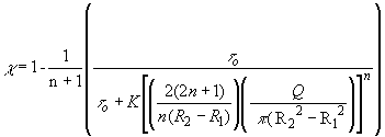 and (100)
![]() , (101)
, (101)
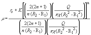 , (102)
![]() (103)
(103)
On substituting the Eqs. (100), (101), (102) & (103) in equation (99) we obtain,
Equivalent Reynolds number,
 (104)
(104)
While the critical equivalent Reynolds number is given by;
 (105)
(105)
Where,
![]() ,
,
![]()
For ![]() the flow is considered laminar while,
the flow is considered laminar while,
For ![]() the flow is considered turbulent
the flow is considered turbulent
(i) Frictional Pressure Drop for Laminar Flow:
The pressure drop is calculated using the following Fanning expression:
 (106)
(106)
While the friction factor is determined by the following equation:
![]() (107)
(107)
Substituting Eqs. (104) and (107) in Eq. (106) we have
 (108)
(108)
Where, c is the correlation coefficient for the circular section.
(ii) Friction Pressure Drop for Turbulent Flow:
The pressure drop is calculated using the following fanning equation:

While, the fanning friction factor is determined by using the relation of Schuh:
![]() (109)
(109)
where v and y are coefficients as shown in the previous section.
The above pressure gradient equations for Laminar or Turbulent flow regime, for both pipe and annular flow can be substituted back into the respective velocity equations for pipe and annular flow, to yield the Velocity distributions of YPL mud in both pipe and annular flow configrations. In addition , we can calculate the shear stress distribution and the shear rates.
Rheology Measurements
Several types of equipment are used for the measurement of mud’s flow properties. Not all are capable of giving information that is useful in predicting circulating pressure losses and other parameters required in the design of a hydraulics program.
Marsh Funnel :
The time it takes for one quart of the fluid to flow through the outlet of the Marsh funnel is called the funnel viscosity. The funnel viscosity for freshwater at 70± 5° F is 26 ± 0.5 seconds.
This test is quick and simple. Unfortunately, the Marsh funnel gives no useful quantitative information about the rheological properties of the drilling fluid. Fluids with widely varying rheologies may all have the same funnel viscosity. A reasonable hydraulics program cannot be developed based on funnel viscosity, although it may be the only flow property specified in the drilling fluids program.
Fann Viscometer:
The Fann viscometer is a concentric cylinder viscometer capable of measuring the shear stress at two or more shear rates. This is by far the most common device used at the rig site and in the laboratories to measure the rheological properties of drilling fluids. The Fann viscometer was designed specifically for use with drilling fluids and the various constants in the rheological models can be measured rather easily.
The following table shows some typical values derived from the use of Fann viscometer measurements.
Parameter Bingham Plastic Power Law Herschel-Buckley
n 1 0.737 0.752
K 26 0.39 0.35
t
o (lb/100ft2) 13 0 1The rheological parameters are quite different, except for the Power Law and Herschel-Buckley models, even though all utilized the same set of viscometer readings. The K value listed for the Bingham plastic model is the plastic viscosity with dimensions of cP. The consistency index, K in the Power Law and Herschel-Buckley models have dimensions of lb×secn/100ft2 and thus look quite different from the plastic viscosity value.
Rheological Oddities
Liquid behavior is largely based on observations of Newtonian fluids, especially water. Therefore, some flow phenomena appearing in polymeric and other non-Newtonian fluids seem quite strange to us. As we know, a rod rotating in a Newtonian fluid (water) generates a slight dip in the region immediately adjacent to the rod due to centrifugal forces, if the rotation rate is high enough. Unlike Newtonian fluids, polymeric liquids and other visco-elastic fluids tend to move upward along the rod. This is known as rod climbing. Housewives and designers of stirring devices often have problems with rod climbing. Rod climbing is caused by the so-called Weissenberg effect.
If pressed through a capillary tube, certain polymeric liquids show a sudden increase in diameter upon exiting the tube. This is known as die swell or extrudate swell. The increase in diameter can reach three times the diameter of the tube. Die swell must be taken into account in polymer extrusion processes.
In contrast to Newtonian fluids, normal stresses can act on free surfaces of certain polymeric liquids. This leads to the tubeless siphon where the non-Newtonian fluid is drawn upward out of a container by a tube, even when the tube is slightly above the free liquid surface. The tubeless siphon behavior isn't just fun but also of technical importance because it's closely linked to the property known as spinnability; a property which is important for manufacturing synthetic fibers.
The explanation of the above phenomena is quite complex but amounts to the following; the long linear molecules that are lined up under the effect of stresses try to go back to their tangled equilibrium state. More detailed explanation can be found in volume 1 of Dynamics of Polymeric Liquids by Bird, Armstrong, and Hassager.
Rod Climbing
Discussion
Imagine inserting a rotating rod into an open container of fluid. If the fluid is Newtonian, its free surface remains relatively flat, perhaps showing a slight dip in the region immediately adjacent to the rod if the rotation rate is high enough. If the fluid is non-Newtonian, however, we see a totally different effect. Now, the fluid not only moves inward toward the rod but upward along the rod itself. This effect is known as rod climbing, and can be quite dramatic.
Rod climbing provides a vivid illustration of normal stress effects, which are responsible for much of the unique rheological behavior we observe in polymeric liquids. The origin of rod climbing can be described by the rubber band analogy.
This time things are a little more complex because the fluid is moving in a circular path rather than a straight line. To visualize the increased tension experienced by the polymer molecules traveling in a circle, imagine cutting a rubber band so that now you have a single strip of rubber. Now cut off a little bit of this strip (say a quarter of the total length) and re-attach the two ends. You now have a smaller rubber band. The rubber band represents the polymer molecules flowing along a circular streamline around the rod. Elastic energy builds up as the flow stretches the polymer molecules. The situation is as if the original rubber band has been replaced by the new shorter rubber band. But the shorter rubber band must be stretched out in order to span the same circular path. This stretching is analogous to the normal stresses experienced by the polymeric fluid moving around the rod.
If you stretch out a rubber band to a larger diameter and let go, it will snap back to its original diameter. In a similar way, the polymeric liquid seeks to dissipate the elastic energy built up along its circular streamlines by contracting radially inward. This inward motion can be quite dramatic; forcing the fluid quite a distance up the rod.
Elastic Effects
Discussion
Most polymeric materials are visco-elastic; that is, they exhibit both viscous behavior (like a liquid) and elastic behavior (like a solid). This extra elastic character can give rise to some interesting effects. Here we see an example of elastic recoil, which occurs when a polymer is stretched by an external force. This stretching causes elastic energy to build up within the polymer molecules. Once the force is removed, this energy is released and the molecules snap back to their original configurations. This can be visualized by imagining each polymer molecule as a tiny rubber band. If the rubber band is stretched and released, it snaps back to its original shape.
Imagine a polymer fluid is poured from one container to another (the fluid flows, illustrating its viscous character). If the flowing stream is cut with a pair of scissors, we find that the top part of the fluid returns back to the beaker, from which it was poured (elastic recoil).
Time Dependent Behavior
Drilling fluids often exhibit time dependent behavior. At constant shear rate, the effective viscosity can change with time until equilibrium is reached. If the viscosity decreases with time at constant shear rate, the fluid is called thixotropic. Drilling fluids are usually thixotropic. Thixotropic fluids can exhibit gellation during static periods when they become more "solid-like". Such behavior is the result of interactions between particles in the fluid which increase in intensity as the length of the static period increases. The magnitude of these interactions measured with the Fann viscometer is called gel strength. The gel strength of a drilling fluid is usually measured after static periods of 10 seconds and 10 minutes, although other time intervals ranging from zero seconds to 30 minutes are often used. The gel strength will build with time but will eventually reach a maximum.
Temperature and Pressure Effects on Rheological Properties
The rheological properties of drilling fluids are often measured at ambient pressure and at a fixed temperature, usually 120° F or 150° F. Other temperatures, like room temperature or flowline temperature may be used. It is always better to use at least one of the two standard temperatures during the course of drilling a well, so that valid comparisons can be made between measurements.
Rotational viscometers exist for the measurement of rheological properties at elevated temperatures and pressures but these are costly devices which typically are only operated in the laboratories and are rarely if ever used at the rig site. While it may be desirable to know the rheological properties under downhole conditions, such data are usually not available. Because of this, surface measured properties, i.e. those measured in a Fann viscometer at 120° F or 150° F and at ambient pressure, are used as the basis for hydraulics calculations, hole cleaning predictions, etc.
Nomenclature
Field units:
Dp/dL (pressure loss): psi/ft
r (density): ppg
m p (plastic viscosity): cP
m (viscosity): cP
m t (turbulent viscosity): cP
Q (flow rate): gpm
L (Length): ft
D (Diameter in annulus): in
d (diameter in pipe): in
v (velocity): ft/min
K (consistency factor): or
Consistent units:
Dp/dL (pressure loss): Pa/m
r (density): kg/m3
m p (plastic viscosity): kg/m s
m (viscosity): kg/m s
m t (turbulent viscosity): kg/m s
Q (flow rate): m3/s
L (Length): m
D (Diameter in annulus): m
d (diameter in pipe): m
v (velocity): m/s
K (consistency factor): 